I recently connected my garage door to the Internet using an ESP8266. More on that topic in another post. This post covers some research I did after discovering that one of my garage doors opened every time the power was removed from the ESP8266 and re-applied.
Background
My WiFi garage door opener is simply a pair of relays connected to ESP8266 GPIOs. I essentially chose which specific GPIO pins to use at random; D0 and D5. The relays are triggered by a high logic level, which I naively assumed would be safest, since a non-operational ESP8266 wouldn’t trigger them. Evidently there are some glitches on the ESP8266 GPIOs when it is first powered on, since one of the relays does trigger for a short time when the system is powered on. I set out to capture the ESP8266 GPIO signals, first using a logic analyzer, and later using an oscilloscope.
Investigation
Note: Most of this post uses NodeMCU’s GPIO numbering, which is different than ESP8266 raw GPIO numbering.
I started out by capturing the state of the two relevant ESP8266 GPIO pins using a logic analyzer. This showed no difference in behaviour; both pins started low while the ESP8266 was powered off, then briefly pulsed high while the ESP8266 booted, then returned low when my Arduino application began to run and explicitly set the GPIOs to output a low value:
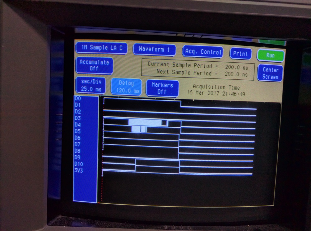
Above: ESP8266 GPIO digital behaviour at boot, when running a simple Arduino application that does nothing except to set all GPIOs to output a low value at boot.
This behaviour was puzzling since the two relays in the system were identical, yet only one actually triggered. Swapping the ESP8266 GPIOs between the relays showed that the behaviour followed the ESP8266 GPIO signal, and not the relay. Hence, I set out to investigate the GPIO output behaviour in even more detail. Viewing those GPIOs using a oscilloscope showed a difference; the D0 low output level isn’t 0V, but rather about 1V, whereas D5’s low output value is 0V as expected:
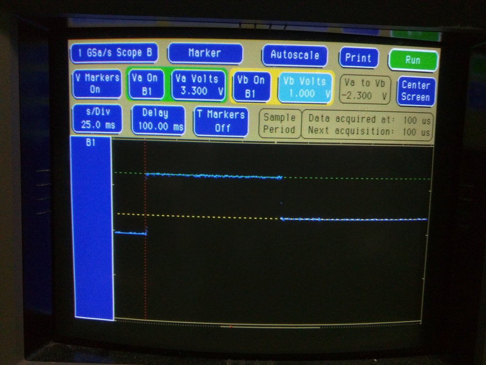
Above: ESP8266 D0 GPIO analog behaviour at boot, when running a simple Arduino application that sets the GPIO to output a low value at boot.
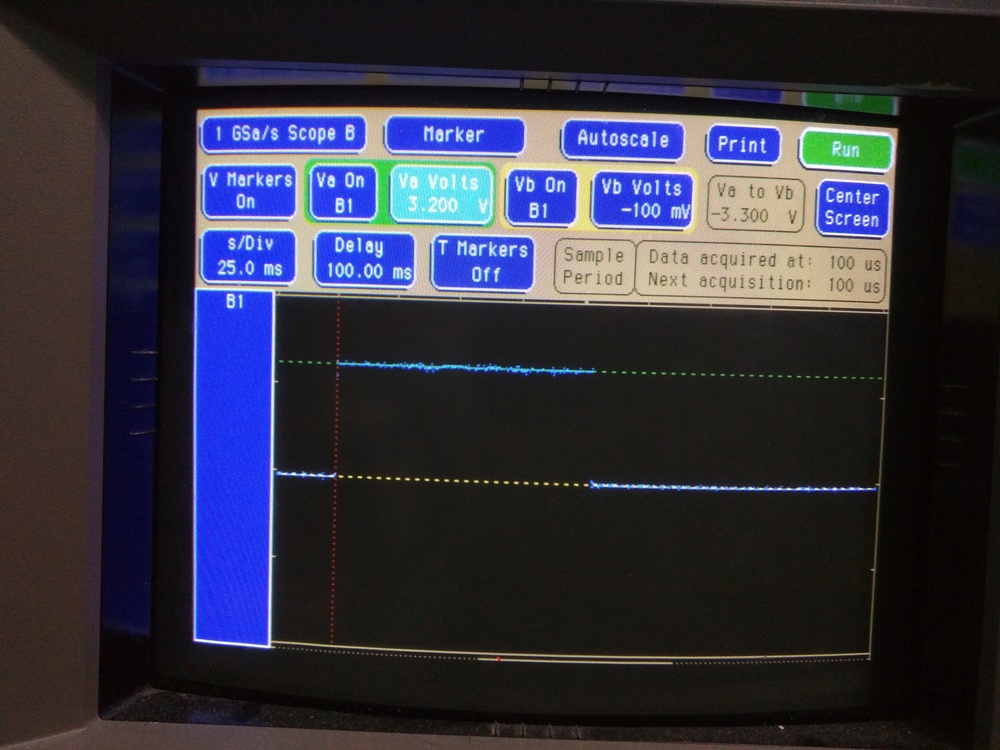
Above: ESP8266 D5 GPIO analog behaviour at boot, when running a simple Arduino application that sets the GPIO to output a low value at boot.
I can only assume that D0’s higher low voltage keeps some capacitance in the relay board charged just long enough to let the relay coil close the relay for a short time, but this soon discharges, releasing the relay again. Evidently the 1V level is below my digital logic analyzer’s Vih (Voltage input high) level.
After observing this strange behaviour, I set out to measure the digital behaviour of all GPIO pins in three situations:
-
When the ESP8266 is powered on in flashing/bootloader mode.
-
When booting into a Arduino application that does literally nothing.
-
When booting into an Arduino application that explicitly sets all GPIOs to output a low value.
I also captured the behaviour of all GPIOs using an oscilloscope in case 3 above.
The logic analyzer configuration includes the ESP8266 3V3 power rail as an additional input signal, and are triggered by a rising edge of this signal.
The oscilloscope traces were triggered by a rising edge of the individual GPIO being measured.
GPIO Behaviour Summary
Here’s a summary of how all the ESP8266 GPIOs behave. Pictures of the analyzer/scope traces are shown below.
| NodeMCU GPIO |
ESP8266 GPIO |
Behaviour Flash Mode |
Behaviour Dummy Arduino App |
Behaviour Arduino Set GPIOs Low |
|---|---|---|---|---|
| D0 | 16 | High | High during boot, falls after ~110ms (to ~1V?) | High during boot, falls after ~110ms (to ~1V) |
| D1 | 5 | Low | Low | Low |
| D2 | 4 | Low | Low | Low |
| D3 | 0 | Low then oscillates | Varies, stabilizes high after ~100ms | Varies, stabilizes low after ~110ms |
| D4 | 2 | Varies, stabilizes high after ~60ms | Varies, stabilizes high after ~70ms | Varies, stabilizes low after ~110ms |
| D5 | 14 | High | High, then low after ~110ms | High, then low after ~110ms |
| D6 | 12 | High | High, then low after ~110ms | High, then low after ~110ms |
| D7 | 13 | High | High, then low after ~110ms | High, then low after ~110ms |
| D8 | 15 | Low | Low, with glitch ~110ms | Low, with glitch ~110ms |
| D9 | 3 | Low | Low until ~50ms then high | Low until ~50ms then high until ~110ms then low |
| D10 | 1 | Low | Low until ~50ms then high | Low until ~50ms then high until ~110ms then low |
Conclusion: GPIOs D1 and D2 are the only safe GPIOs I can use to drive relays if I don’t want them to operate autonomously at boot. I will have to rework my PCB:-(
Future Work
I didn’t investigate GPIO behaviour in all possible cases. The following might be interesting cases too:
-
An Arduino application that explicitly sets all GPIOs to output a high value.
-
An Arduino application that explicitly sets all GPIOs to input mode.
-
Native ESP8266 applications, i.e. not using the Arduino environment.
-
Analog behaviour with more than one type of application.
-
Compare multiple ESP8266 boards to see if the behaviour varies at all. I suspect analog behaviour would be most interesting here.
-
Retest with a weak pull-up/-down attached to each GPIO, to verify whether they’re floating randomly or actively driven by the ESP8266 at boot. In most cases, I’m fairly sure they’re actively driven since the patterns are repeatable. However, best to be sure. Suggested by Anders Sandblad.
Additional Information from Erich Flach
In May 2018, I received an email from Erich Flach detailing an investigation he’d performed into ESP8266 GPIO usage at boot time. Here’s what he wrote:
Dear Stephen,
Thank you for the information given on your website! I’d like to add some explanations about the behaviour of some pins:
A year ago or so, I also investigated on the ESP8266 NodeMCU boot behaviour since I tried to use as much IO as possible. Unfortunately, I don’t have the diagrams etc. from that time, but as far as I remember, I observed the following:
GPIO1, i.e. “TX”, “TXD0”, and GPIO2, i.e. “D4”, “TXD1” have a somewhat strange behaviour showing the following steps at startup:
-
Check level of line TXD0. If it is 1, continue with step 4.
-
Apply the internal pull up resistor to TXD0. If it becomes 1, assume that the line is free. If it remains at 0, continue with step 4.
-
Send (useless) boot loader startup information on TXD0 and continue startup process.
-
Check level of line TXD1. If it is 1, stop everything (!).
-
Apply the internal pull up resistor to TXD1. If it becomes 1, assume that the line is free. If it remains at 0, stop everything (!).
-
Send (useless) boot loader startup information on TXD1 and continue startup process.
So in a few words: Try to send the startup information via TXD0, or TXD1. If this is not possible, refuse to work.
I was really annoyed by the fact that the processor stops to work just because of the (for me) completely useless startup messages. It was hard to believe that the implementation is so silly that it refuses to continue when the lines are just occupied by some external IO.
If you want to check this, it’s rather easy to do by using medium- resistance pull-down or pull-up resistors (22k, or so) to change the line level. Then you may obeserve with the oscilloscope the internal pull-up applied to the line before the data is sent.
Pictures
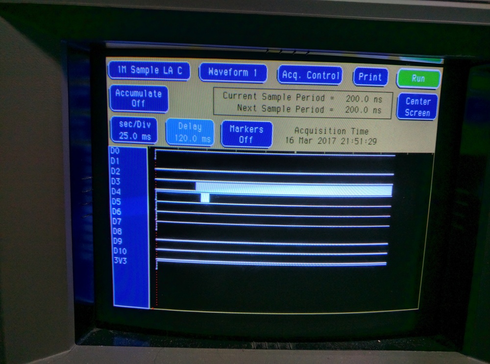
Above: ESP8266 GPIO digital behaviour at boot, with the device forced into flash mode (bootloader) at power on.
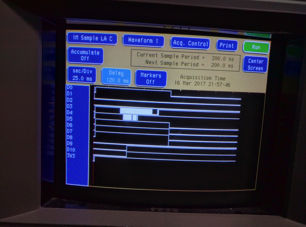
Above: ESP8266 GPIO digital behaviour at boot, when running a dummy Arduino application that does absolutely nothing.

Above: ESP8266 GPIO digital behaviour at boot, when running a simple Arduino application that does nothing except to set all GPIOs to output a low value at boot.

Above: ESP8266 D0 GPIO analog behaviour at boot, when running a simple Arduino application that sets the GPIO to output a low value at boot.
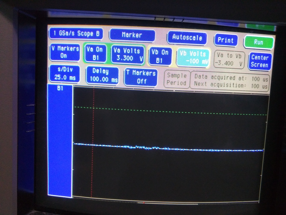
Above: ESP8266 D1 GPIO analog behaviour at boot, when running a simple Arduino application that sets the GPIO to output a low value at boot.
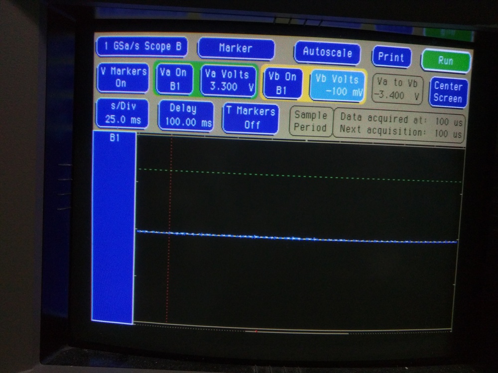
Above: ESP8266 D2 GPIO analog behaviour at boot, when running a simple Arduino application that sets the GPIO to output a low value at boot.
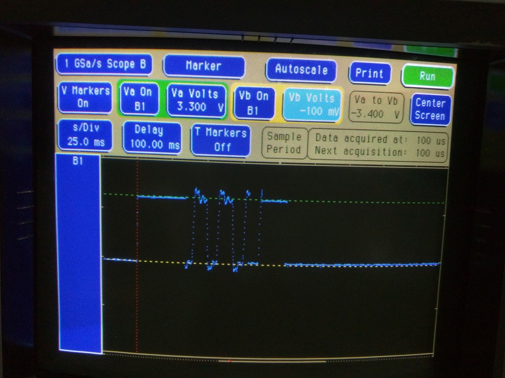
Above: ESP8266 D3 GPIO analog behaviour at boot, when running a simple Arduino application that sets the GPIO to output a low value at boot.
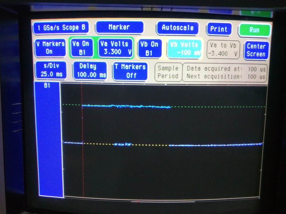
Above: ESP8266 D4 GPIO analog behaviour at boot, when running a simple Arduino application that sets the GPIO to output a low value at boot.

Above: ESP8266 D5 GPIO analog behaviour at boot, when running a simple Arduino application that sets the GPIO to output a low value at boot.
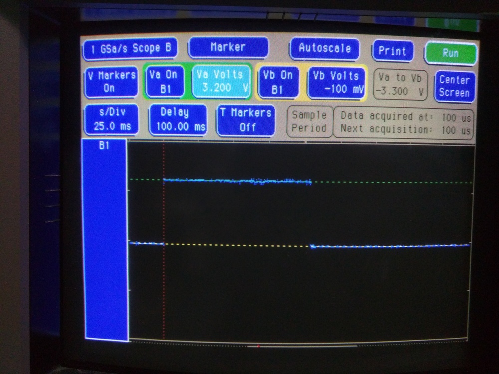
Above: ESP8266 D6 GPIO analog behaviour at boot, when running a simple Arduino application that sets the GPIO to output a low value at boot.
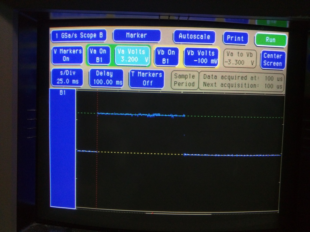
Above: ESP8266 D7 GPIO analog behaviour at boot, when running a simple Arduino application that sets the GPIO to output a low value at boot.
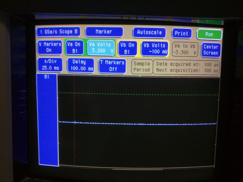
Above: ESP8266 D8 GPIO analog behaviour at boot, when running a simple Arduino application that sets the GPIO to output a low value at boot.
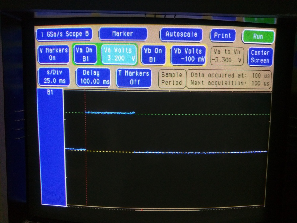
Above: ESP8266 D9 GPIO analog behaviour at boot, when running a simple Arduino application that sets the GPIO to output a low value at boot.
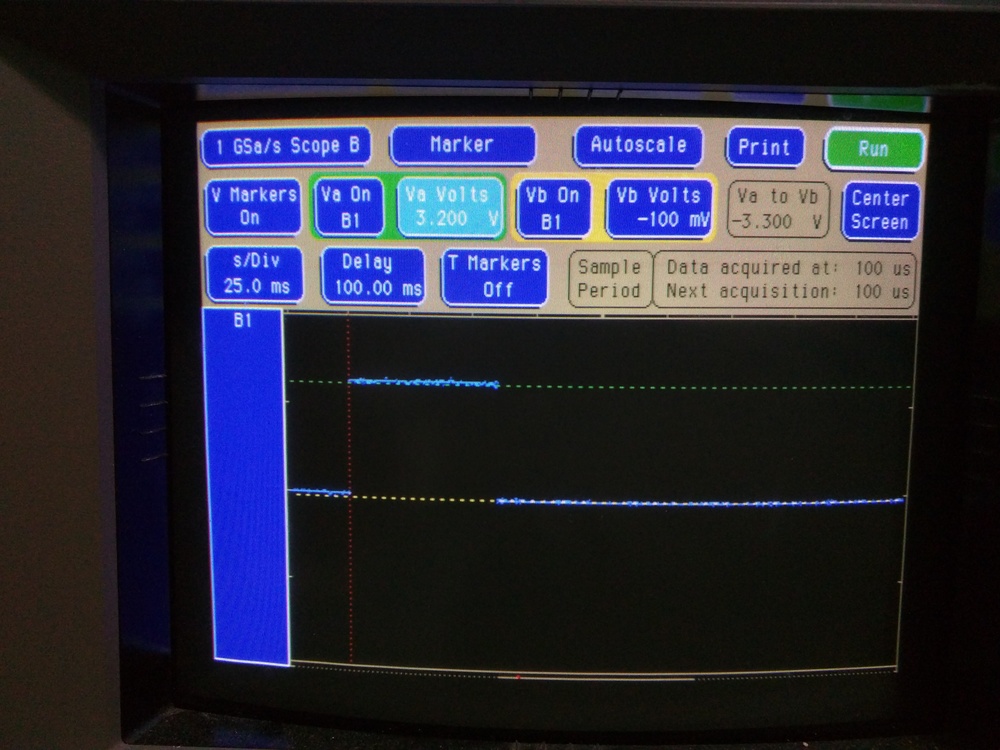
Above: ESP8266 D10 GPIO analog behaviour at boot, when running a simple Arduino application that sets the GPIO to output a low value at boot.
Changelog
2019/05/22: Added info from Erich Flach.
2017/04/03: Add “future work” item to re-test with external GPIO pull-ups/-downs.