Like many people, I often read in bed. However, my wife doesn’t really appreciate me having the overhead lights on when she’s trying to sleep. I decided to solve the issue by building a more targeted reading light. Here’s a brief description of the project.
Project Description
I had plenty of WS2812 (programmable RGB) LED strips left over from other projects, so these were the obvious light source, being readily to hand. These LEDs are mounted on a thin flexible PCB, so I cut out a strip of cardboard slightly larger than the LED strip and glued the LED strip onto it. This gave the strip a more rigid structure. I then taped the cardboard strip to my bed’s headboard, point downwards where I sleep. A later enhancement to the project may to find a triangular strip of wood to back the LED strip, and permanently install it using glue or screws; the duct tape tends to peel off a little and needs to be manually pushed back into place. Here’s a look at a section of the LED strip:

The LED strip needs to be controlled by some form of micro-controller; it needs to be sent commands to configure each LED’s color and brightness. I had a Sparkfun Arduino Pro Mini hanging around and selected that. Even though I’m powering the LEDs with 5V, and this micro-controller is a 3.3V device, I found the LEDs had no issue receiving and processing the commands.
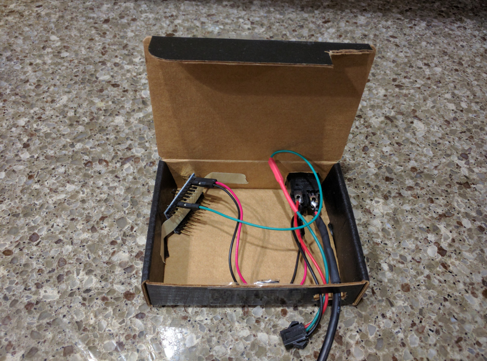
I mounted everything up in a small old cardboard box that probably housed some electronic components that I’d ordered from a website long ago; very similar to Sparkfun’s red cardboard project boxes. Here’s a look inside the project box:

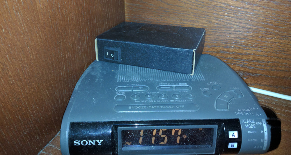
As you can see, I used a switch to cut power to the Arduino. Whenever the system is powered on, the Arduino simply turns on all LEDs to a low-brightness white. Later, I intend to add some push-buttons to control brightness, color, and/or the number of LEDs that are turned on. Perhaps I’ll even replace the Arduino with an ESP8266 to allow WiFi control, but that’s probably going overboard. Here’s a look at the box once it’s closed up and perched on top of my alarm clock radio, with the wire to the LEDs taped along the rear corner of the shelf:

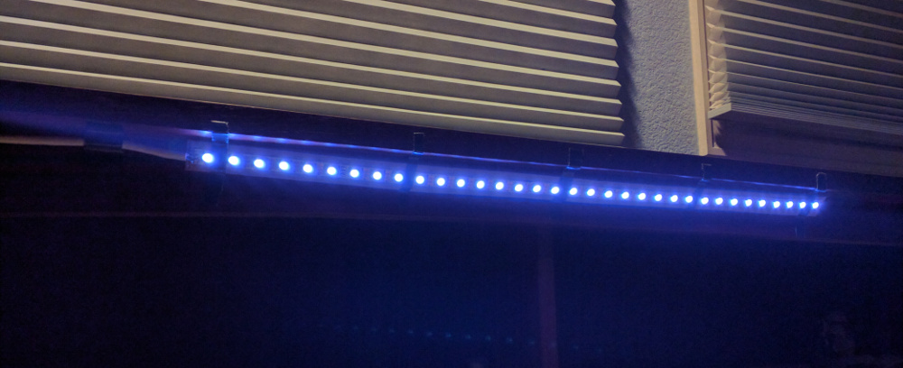
Below is a picture of the system in the dark:

Bill of Materials
- 5V USB charger
- 6’ USB power cable
- DPDT switch
- Small cardboard box
- Arduino Mini Pro 328 3.3V
- 0.1” male headers for the Arduino.
- A few wires for internal project box wiring. Wires with 0.1” female headers are best since these can be plugged directly into the Arduino on one end, while the connector on the other end can be cut off and the wire soldered elsewhere.
- A few feet of e.g. Ethernet cable, to connect the LED strip
- WS2812 LED strip
- LED strip power connector (JST SM 3-pin), one male and one female
- Cardboard backing for the LED strip.
- Craft glue
- Craft knife
- Wire cutters
- Wire strippers
- Soldering iron and solder
- Heat shrink
- Heat gun
Brief Construction Instructions
Here’s a rough description of how I built the project:
- Write a trivial Arduino sketch (program) that turns on the appropriate number of LEDs to a low-brightness white color. I used brightness 30 (out of 255). You may want to experiment. I based my program on Adafruit’s WS2812 test sample sketch, which uses the Adafruit NeoPixel library. Program the Arduino with this program. Below is the code I’m using right now. If/when I get around to adding more features, I expect I’ll publish it on github.
#include <Adafruit_NeoPixel.h>

#define NUM_LEDS 34
#define DATA_PIN 13
#define BRIGHTNESS 32

Adafruit_NeoPixel strip = Adafruit_NeoPixel(NUM_LEDS, DATA_PIN, NEO_GRB + NEO_KHZ800);

void setup() {
  uint32_t c = strip.Color(BRIGHTNESS, BRIGHTNESS, BRIGHTNESS);
  for (int i = 0; i < NUM_LEDS; i++)
    strip.setPixelColor(i, c);
  strip.show();
}

void loop() {
  delay(1000);
}-
Cut LED strip to length, being careful to cut only at the marked divisions between the “cells”.
-
Lay the LED strip onto a piece of cardboard and mark it to show the length/width that needs to be cut out. Remove the LEDs and cut out the cardboard backing strip.
-
The rear of the LED strip is usually mildly adhesive and covered by a removable strip of paper. Remove this paper, cover the LED strip with some extra glue, and apply the strip to the cardboard backing. I clamped mine in place using binder clips until the glue dried.
-
Measure a length of cable to connect from the mounted LEDs to the controller box. Solder one end of the wire onto the LED strip.
- Cut holes into the project box for:
- The power switch.
- The power inlet cable.
- The LED power/data cable.
-
Cut the device end off of the USB cable, thread it into the project box through the power hole, and out through the switch hole.
-
Solder the two wires of the power cable to separate poles of one side of the DPDT power switch.
-
Solder two short wires to the other side of the DPDT switch, and thread those back into the project box.
- Solder a female JST connector to:
- The output side of the DPDT power switch. You may wish to wrap the switch pins in heat shrink.
- A wire with a female 0.1” connector. You may wish to heat-shrink the connection.
-
Mount the switch into the project box, and thread the female JST cable out of the other hole in the project box.
-
Connect the wires from the power switch to the Arduino header’s power input pins.
-
Connect the control wire from the LED connector to one of the Arduino’s data pins.
-
Tape the Arduino into the project box so that it won’t move around and short on
-
Solder a male JST connector to the end of the LED power/control wire.
-
Close up the project box, and install it its final location.
-
Connect the LED strip’s JST connector to the JST connector poking out from the project box.
- Plug in the power to the project box. Behold your new reading light!
Changelog
2017/03/22: Embedded the Arduino code in the article.
2017/03/21: Fixed various typos. Cropped and scaled images.